Thanks very much for the help!
I obtained the book (fifth edition) and already read whole section 2.1 (Band pass and Low pass Signals).
That was exactly what I was looking for.
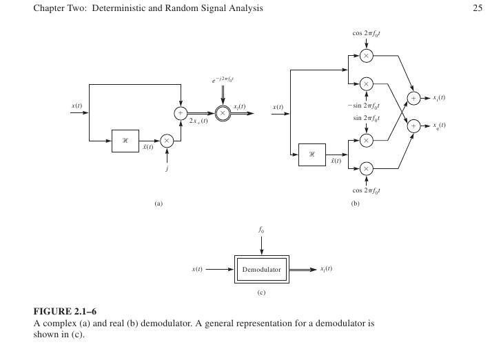
I have one more doubt. Figure 2.1-6 in page 25 shows a real demodulator (I attached the figure here).
This is not the same block diagram of the demodulador that we have inside Elonics E4000 Tuner (zero-IF demodulador).
We don't have a Hilbert transformer inside the zero-IF demodulator. We have just two paths, one multiplying by cos() and the other by sin().
Perhaps the Hilbert transform is implemented by handling the I and Q components as a complex number I+jQ inside GNU Radio?
Can someone please explain to me how the zero-IF demodulator is related to the real demodulator shown in the book?
Thanks very much again,
Lucas Lorenzi Ingles