Description: PNG image
|
| From: | Gayathri Ramasubramanian |
| Subject: | Re: [Discuss-gnuradio] GR, USRP, and GPIB measurements |
| Date: | Fri, 15 Aug 2014 17:08:53 -0700 |
You need to be careful with the WBX as input power above -20 dBm could damage
the 2nd stage RX amplifier. Per the data sheets, the absolute maximum input
power of the 2nd stage amp is below the saturated output power of the 1st
stage amp.
1a) Yes, only valid for linear range.
1b) The device is always going to generate IMD, so it really depends on how
much error you can tolerate. The IMD3 grow at 3x the rate of the main
tones, so for a slow gain compression, the error added to the IMD levels
won't be much compared with how fast they grow. On my plots, -30 dBc is
where the single tone power (visually) starts to deviate from linear.
2) Negative of the difference. The IMD are always going to be negative dBc,
where the "c" means referenced to the carrier.
3) Optional, and tied to the daughterboard, specifically analog imparments
in the I/Q sections. I don't know the specifics; maybe ask on the USRP
list. I think each correction file is serialized by the daughterboard,
which make sense if you are running several USRP from one host.
Thanks,
Lou
KD4HSO
Gayathri Ramasubramanian wrote
> - uhd_cal_rx_iq_balance> Thanks for doing the TX side one tone and two tone tests for USRPN210. It
> helps me get a reference.
>
> 1) When I did the test for finding out the calibration factor, I found it
> was a constant value ntil a certain range and after that it dipped (e.g
> ard
> -8 dBm input power @ 400 Mhz). I image this is point near the saturation
> /compression region of the device. This was observed on 5 USRPN210+WBX
> devices that I tested.
> a) So I understand that this calibration factor is valid only in the
> linear
> range. Is it correct?
> b) if so, I should not use the calibration factor to turn the IMD
> products'
> value on FFT to dBm using this factor as they occur only when the device
> is
> operating in the non linear range.
>
> Please let me know if my understanding is right.
>
> 2) You told me to plot the IMD plot with difference of power between
> fundamental tone and the IMD product power @ harmonc freq. i.e [power @
> F1
> - power @ (2F1-F2)] . But this is coming as a +ve value for me while your
> plot shows the Y axis on a negative scale. Would this also be might due to
> the attenuator you are using? or should I consider the negative of the
> difference?
>
> 2) Also you have told to run the UHD calibration routines should be run
> for
> the N210+WBX:
>
> - uhd_cal_tx_dc_offset
> - uhd_cal_tx_iq_balance
>
> Are these mandatory or optional? Do they affect the daughter board or
> mother board of the device? The devices I use are for common use in a lab
> and hence it is preferable not to change any of the configurations for
> specific use for long term. Hence my question.
>
> As per the information given at
> http://files.ettus.com/manual/page_calibration.html#calibration_ it seems
> that it more tending towards the WBX board operation. Also the factors get
> stored in the machine they are connected to. So in case we want to run the
> USRPN210 device with old configuration, it would be ok to just delete the
> files or run it from some other machine? Is this correct?
>
> Can any random number be specified for a serial number if not detected
> from
> the device or any specific format is to be used ( i.e min number of digits
> & alphabets etc)
>
>
> Kindly clarify the above points.
>
>
> Thanks again
>
> Regards
>
> Gayathri
>
> __________--
> Discuss-gnuradio mailing list
> Discuss-gnuradio@
> https://lists.gnu.org/mailman/listinfo/discuss-gnuradio
View this message in context: http://gnuradio.4.n7.nabble.com/GR-USRP-and-GPIB-measurements-tp49727p49901.html
Sent from the GnuRadio mailing list archive at Nabble.com.
_______________________________________________
Discuss-gnuradio mailing list
address@hidden
https://lists.gnu.org/mailman/listinfo/discuss-gnuradio
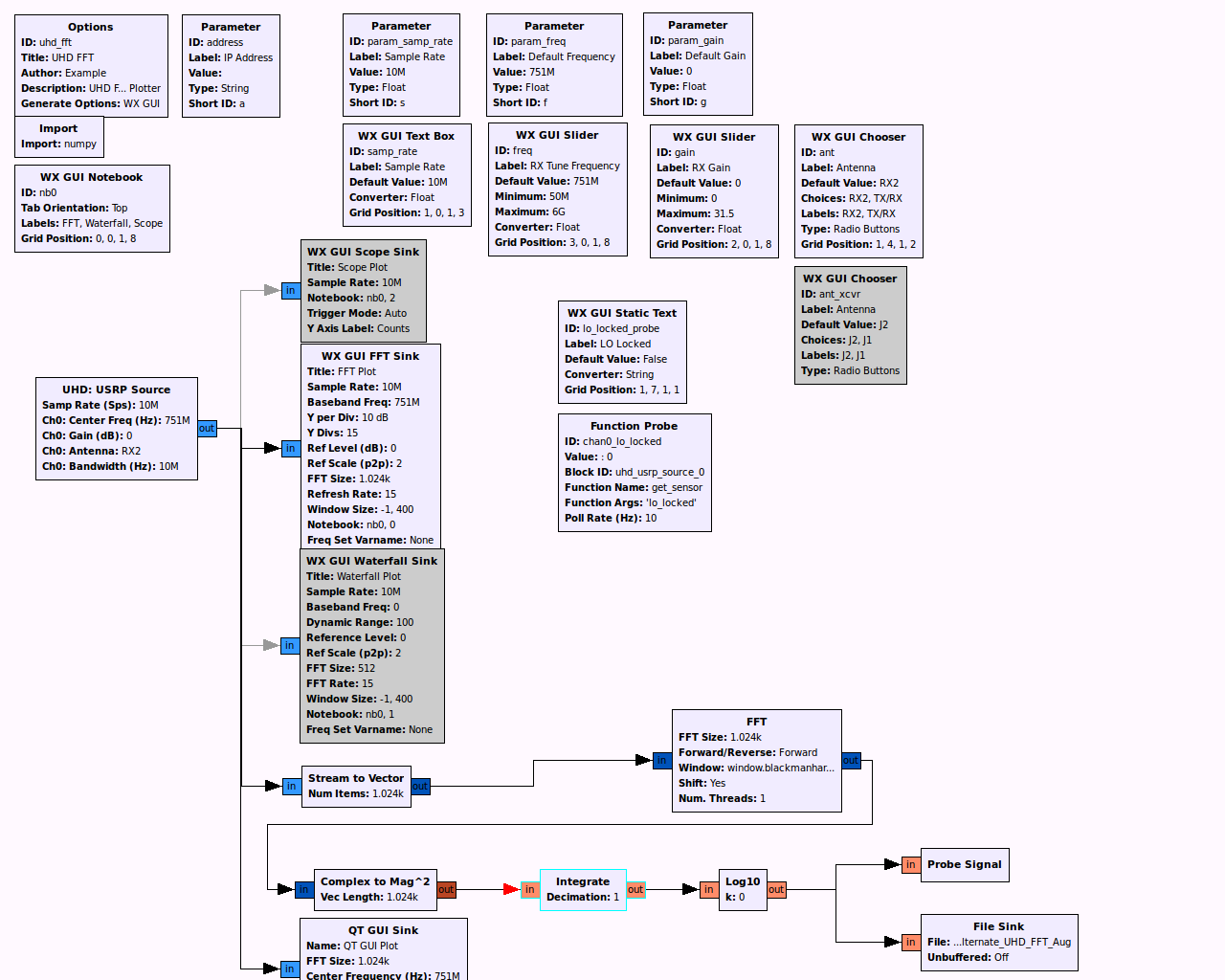
![]() uhd_fft_DK.grc.png
uhd_fft_DK.grc.png
Description: PNG image
![]() uhd_fft_DK.grc
uhd_fft_DK.grc
Description: Binary data
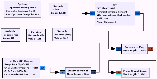
![]() flowgraph screenshot.png
flowgraph screenshot.png
Description: PNG image
| [Prev in Thread] | Current Thread | [Next in Thread] |