In the figure above, I've marked a timing difference between them with arrows.that's only natural. There's filtering involved, hence you get a delay.
Although I adjust a timing difference between them, a waveform after the resampler seems ugly.I still beg to differ :) It looks like a band-limited interpolated version of the signal below.
In this situation, a decision maker may make a false decision, I think.That really depends on the decision maker, but I can see your point. For me, this looks like BPSK, and I'd say with a very modest high pass filter, and a 0 threshold, things might look pretty OK :)
So the thing is: there's nothing stopping you to implement an N/M interpolation by repeating with N and then using a decimating FIR with a decimation factor of M; try that, it might really suit you better.
Best regards,
Marcus
On 07/25/2015 08:12 AM, Jeon wrote:
Jeon.Thanks you Tom and Marcus.Yes, well... I meant that I've also checked FFT but a picture of it was in another PC so I couldn't attach it when I was writing the previous post.
Sorry about that. And I am currently using N210.
Today, carrying on from the yesterday, I've replaced a square wave signal source block with either a random source with a range of [0, 2) block or a custom source block from my module
and made
In the figure above, I've marked a timing difference between them with arrows.
Although I adjust a timing difference between them, a waveform after the resampler seems ugly.
Yesterday, a waveform was quite acceptable since it's not a (pseudo-)random signal, but an alternating square wave.
In this situation, a decision maker may make a false decision, I think.
But it can be different if I connect USRP at the end of the flow graph.
So I'll try both of them with various parameters, see the results/differences and post something if I make some progress.
Regards,
2015-07-24 23:00 GMT+09:00 Marcus Müller <address@hidden>:
Hi Jeon,
what USRP are you using?
You're right: The point is that only integer factor of the USRP's master clock rate can be used.
So for example, if you're using the USRP2 or N210, the master clock rate would be fixed at 100MHz.
That would explain the rates you're seeing. (3.703..MS/s = 100MHz/27, 7.692...MS/s = 100MHz/13, 14.2857 = 100MHz/7)
Well, obviously: If you expect e.g. a 3.75MHz signal sampled at 15MS/s to have a period of 4 samples, and it has a period of 3.8something samples, you will see a frequency offset. Whether your application can correct that is up to the design of the application.
What I concern is, will such differences between given sampling rate and tuned sampling rate make a big difference on a waveform, throughput and performance? I don't think it would make a big difference since ratio of differences are less than 5 percent.
But it would be better to know about it before I run a real experiment.Well, frequency offset is relatively easy to model, so you might even be able to translate that directly into error probabilities based on theory alone.
1. 200 kHz signal -> rational resampler (interp: 15M, decim: 200k) -> USRP (15 MHz)These waveforms look perfectly normal to me! I can't imagine a digital receiver that would have problems with that little overshoot at each transition.
2. 200 kHz signal -> rational resampler (interp: 75, decim: 1) -> USRP (15 MHz)When I run those three, first two using rational resampler blocks gave me ugly waveforms.
3. 200 kHz signal -> repeat (interp:75) -> USRP (15 MHz)
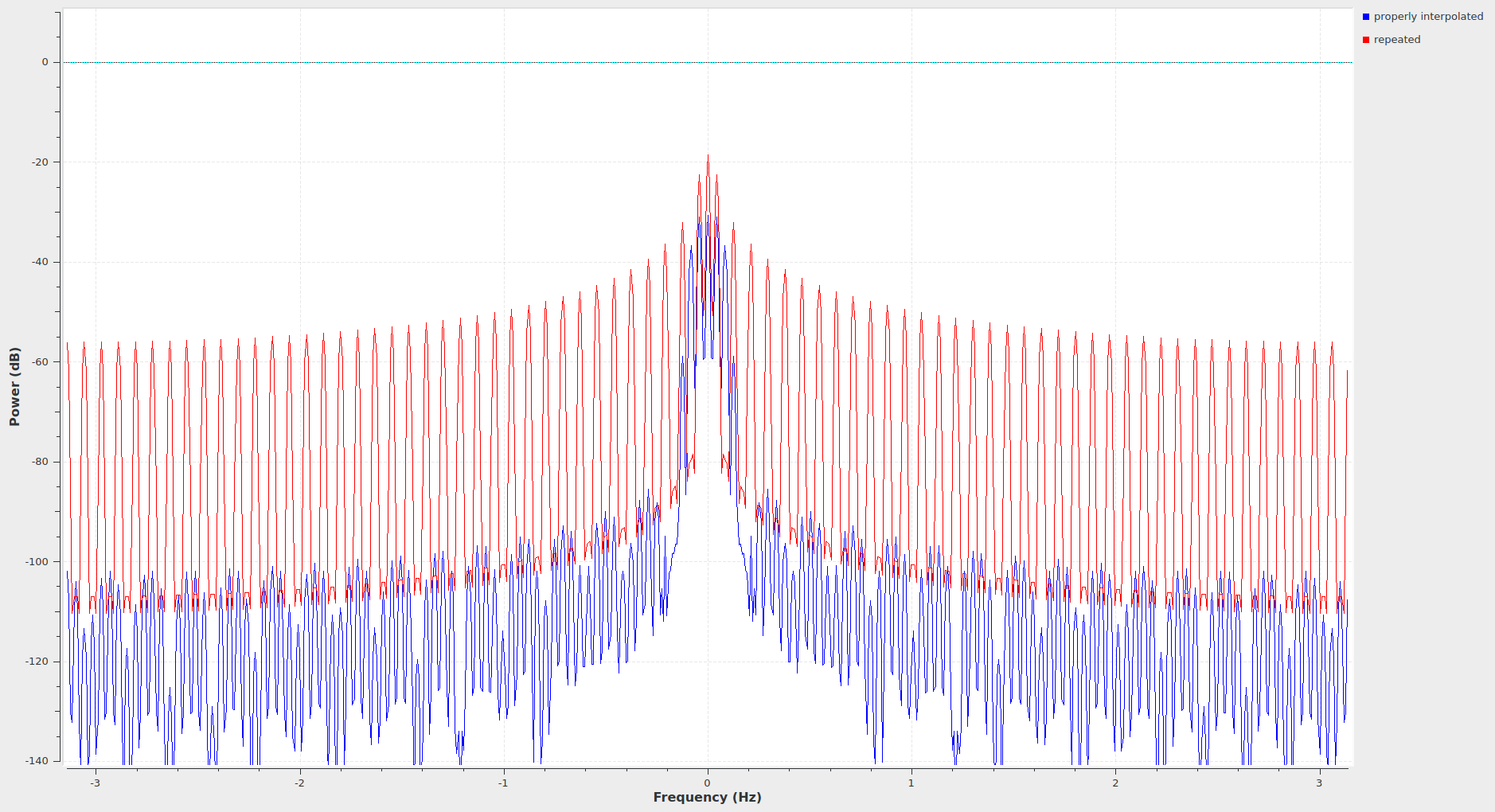
(Forgot to take a picutre of FFT, sorry.)That's actually sad, because you would have noticed that the waveforms you think look ugly actually look more beautiful in frequency domain: (don't interpret x-Axis as Hz, but as numbers (-pi; pi))
That's just basic DSP, hapening here:
All these strong red peaks outside the original signal's bandwidth shouldn't be there -- after all, the signal you fed in had 1/75th of the output nyquist bandwidth!
Interpolation needs an anti-imaging filter to suppress the spectral images -- in DSP, you seldom really want to have the sharp transitions when you interpolate something. That interpolated signal should only occupy its original's bandwidth, usually. Hence, you filter to b_nyquist/interpolation.
Finite filters can't have infinitely sharp passband edges, so you'll see attenuation for the frequencies that are very close to the nyquist frequency of the input signal. In your case, the abrupt change from 0 to 1 is exactly that, a signal with all the input bandwidth as spectrum, so there's the highest frequency parts of that attenuated a little bit, and you see these oscillations near the edge.
Since every physical system has low pass characteristics, you can typically find high tolerance against this in baseband transceivers; most of them just care about whether the signal has passed the threshold or not. Overshoot is ignored, or even "slightly welcome" because it antagonizes capacity-caused slowness (ie. the low pass characteristics of the signal fits the low pass characteristics of the device).
So, long story short: this is good, and normally, you'd just go with it. The implementation GNU Radio uses for the fractional resampler is a minimum mean square error interpolator FIR, and unless you'd have a specific metric that mathematically makes that a bad choice, I'd say it's pretty optimal.
So in the cases where just using the repeat block is not an option, you'll either need to repeat with changing factors (e.g to interpolate by 1.5, how long should your "high" period be? 1 sample? 2 samples? neither can be right, so you start changing that continously, effectively altering the periodicity of your signal, making clock recovery on the receiver side harder), or this filtering is *exactly* what you want
Next thing is: The USRP interpolates with anti-imaging filters itself, so you'll end up with these overshoots/oscillations, anyway (but only if you zoom in with an oscilloscope closely enough).
Best regards,
Marcus
_______________________________________________
Discuss-gnuradio mailing list
address@hidden
https://lists.gnu.org/mailman/listinfo/discuss-gnuradio
_______________________________________________ Discuss-gnuradio mailing list address@hidden https://lists.gnu.org/mailman/listinfo/discuss-gnuradio