Hello Kyeong,
Thank you so much for a clear explanation. Yes, I have been thinking of simulation terms and been avoiding the real world hardware issues the receiver has to deal with.
I really appreciate your response.
Thanks and Regards
Ashish
On Thu, Dec 27, 2018 at 9:36 PM Kyeong Su Shin <address@hidden> wrote:
Hello Ashish,
(TL;DR: GNU Radio applies root-raised-cosine (RRC) filter when modulating/demodulating digital symbols.)
Longer version:
What you have been doing is a simplified simulation of digital communication systems. GNU Radio is designed to handle real-world hardware, like SDR transceivers. Real-world hardware cannot be implemented like that, because:
1. The signals are band-limited (cannot instantly jump from one constellation point to the other), and
2. The receivers and the transmitters are not synchronized perfectly (may have time/phase/frequency offsets).
You can configure GNU Radio to transmit signals as like in your previous simulations (1 sample / symbol), by simply replacing the 'constellation modulator' block with your own implementations. That may work in some cases. However, in that way, you cannot preciesly shape the waveforms of the signals that you are transmitting. As I mentioned earlier, the signals will be band-limited, and if you do not shape your signals, the hardware will (in an uncontrolled manner). That could make the implementation of the receivers difficult.
Now, that may still work. The problem is much worse if the receiver is sampling at the same rate, however. If the sampling rates of the receivers are equal to the symbol rates of the transmitters, that means that there is no headroom for synchronizations (frequency, time, phase).
Imagine a case where a transmitter's master clock and the receiver's master clock are slightly off (a common real-world hardware imperfection). That means that the actual center frequencies of the transmitter and receiver will be a slightly off (usually a few kHz). Now, if the receiver was sampling at the symbol rate of the transmitter, the receiver cannot reconstruct the data from the transmitter because it simply does not have the right information. It has to sample at a faster rate to be able to correct the error (frequency synchronization) and recover the data. An integer multiple of the transmission symbol rate is preferred, due to the easiness in the processing. And do not forget that this is just a part of the synchronization problem - you also have to deal with other real-world issues.
Due to such problems, GNU Radio (and most other real-world digital transceiver systems) shape waveforms of the transmitted symbols in the digital domain, and use somewhat slower symbol rate than the sampling rate. Root-raised cosine (RRC) filters are used for the pulse shaping, due to their nice characteristics.
The constallation plots that you are seeing are not messed up. Those are what you are actually transmitting. I guess what you want are the 'demodulated' constellations, after synchronizers and equalizers of the receiver, decimated to 1 sample per symbol.
Regards,Kyeong Su Shin
보낸 사람: Ashish S <address@hidden> 대신 Discuss-gnuradio <discuss-gnuradio-bounces+ksshin=address@hidden>
보낸 날짜: 2018년 12월 28일 금요일 오전 2:00
받는 사람: address@hidden
제목: [Discuss-gnuradio] Question on Samples/Symbols (sps) in "PSK Demodulation" tutorial.Hello everyone,I have some confusion on samples/symbols concept in GNU Radio and it's driving me crazy when I start to overthink on this.
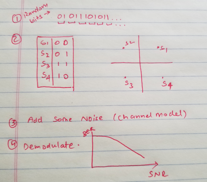
How I did PSK modulation during my studies was :Generate random bits, group them according to modulation type (here considering QPSK) and then pass it through some channel and then demodulate it.this whole thing runs in a loop for different values of SNR and I used to plot BER vs SNR. Here is the quick snapshot
Running through the PSK modulation(example provided on GNU radio tutorials)flowgraph : mpsk_stage1.grcWe have a random source which outputs 10k samples in the range of [0,255] as a byte stream and constellation modulator outputs complex baseband signal (based on constellation object mapping provided)This constellation modulator has samples/symbols as an input which needs to be >=2 .
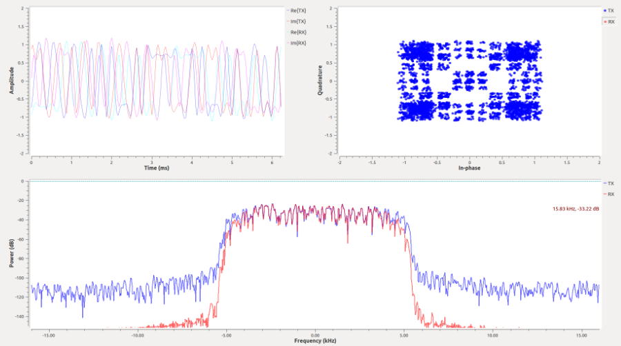
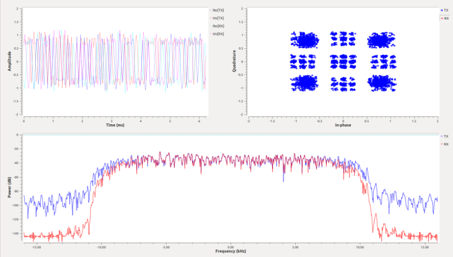
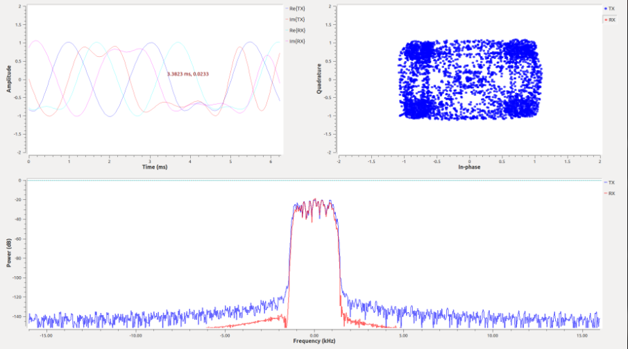
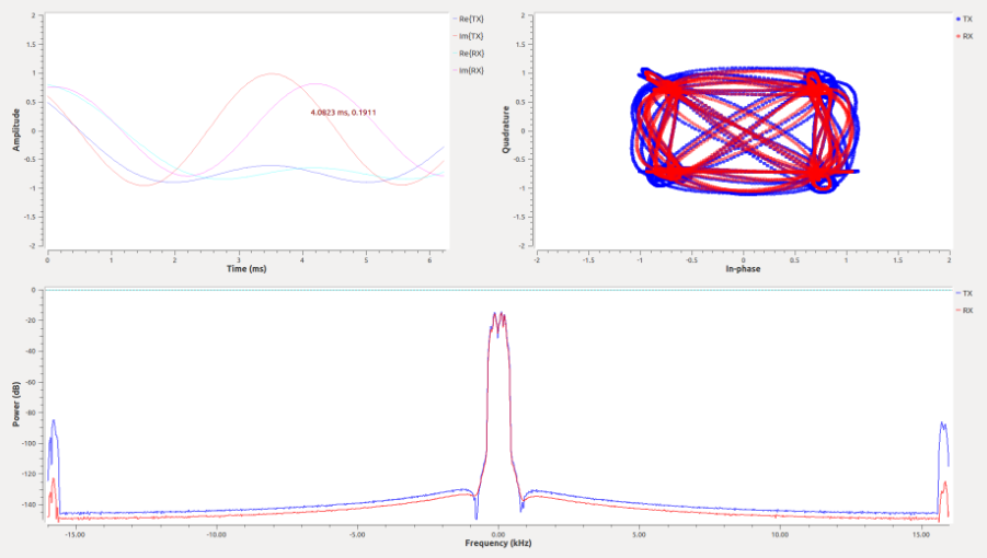
why is this >=2 and since random source repeats its 10k samples every period , can't it just group two bits and map as a symbol. ?When I tend to increase the SPS from 2 to 64 keeping everything the same , the constellation starts to mess up and the fft plot goes narrower. Can anyone of you give an insight into this, please ?
When SPS is 4
When SPS is 2
When SPS is 16
When SPS is 64
Ashsih