Hi Marcus,
Thanks for remembering and responding! I am currently in multiple conundrums over this scheme going to work or not.
I am trying to do exactly what you said with a slight modification now.
I was trying to do BPSK with {0,1} bits being mapped to amplitude (and correponding phase of 180 ) - {1,-1}.
But since I don't transmit for a while as you have noticed in xxx above, there is no reference for receiver to find out the change in phase.
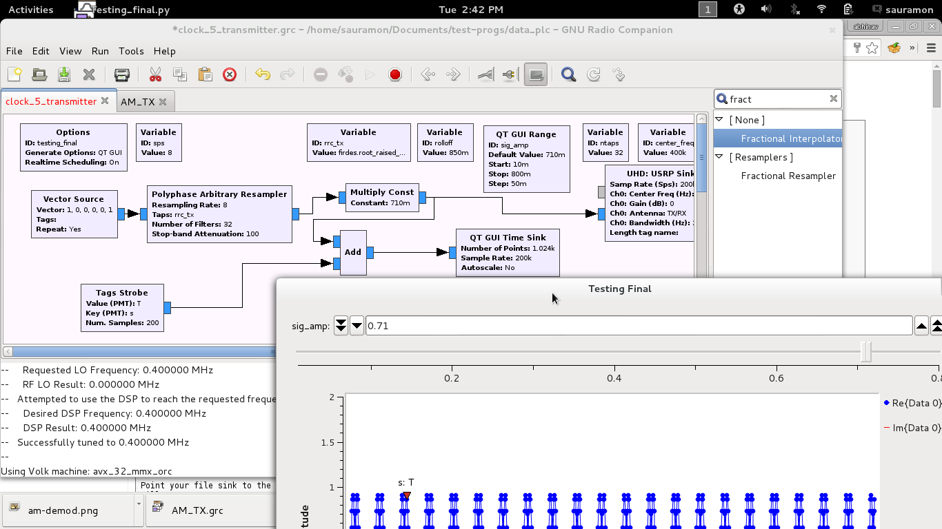
I have now fallen to doing PPM where I map {0,1} bits to {101,11} symbols on the transmitter side, where 0 in 101 is equivalent to x 1x1 as I don't transmit anything in that slot too.
so now the above transmission as you wrote will look like :
xx11xx101xx101xx101xx11 => xx11xx1x1xx1x1xx1x1xx11.
The transmitter-with-usrp.png shows my transmitter.
I tried few things for the receiver and failed.
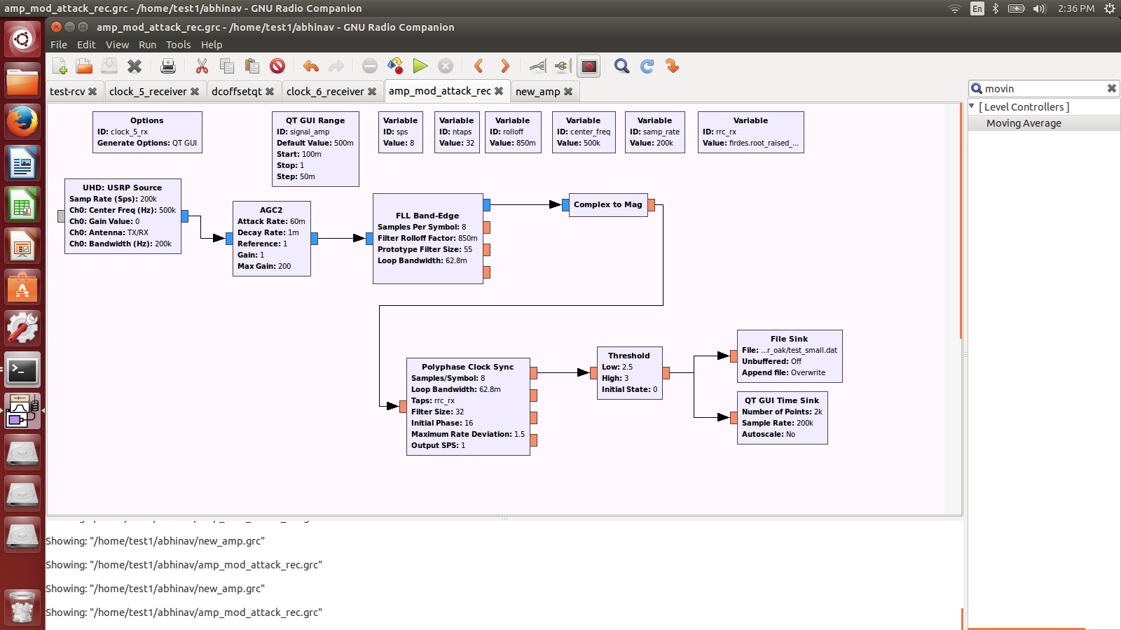
1) I tried polyphase-demod.png where I skipped the decision making decoder and added AM demodulation part (complex_to_mag ..) but kept the polyphase clock sync and FLL Bandedge, AGC2 -- I had learned these block from previous code dives into gnuradio codebase.
2) I tried am_demod_fll.png, which uses FLL Bandedge filter, Polyphase Clock sync to recover timing of symbol
I think both of them might have problems as there is hardly any carrier present when i transmit sparsely with 1 in between thousands of 0s amplitude at transmitter.
I assumed that the receiver will get the same number of x (which I would translate to 0 when I decode) between two 1s transmitted, but I see lot many x or 0s between 1s and hence I can't decode anything meaningful.
I contemplate that this is due to clock drift at receiver ? and it looses track of and spits too many 0s ... is it true ? or is there something else I am doing wrong in my receive chain to not get the right answer.
Hence,
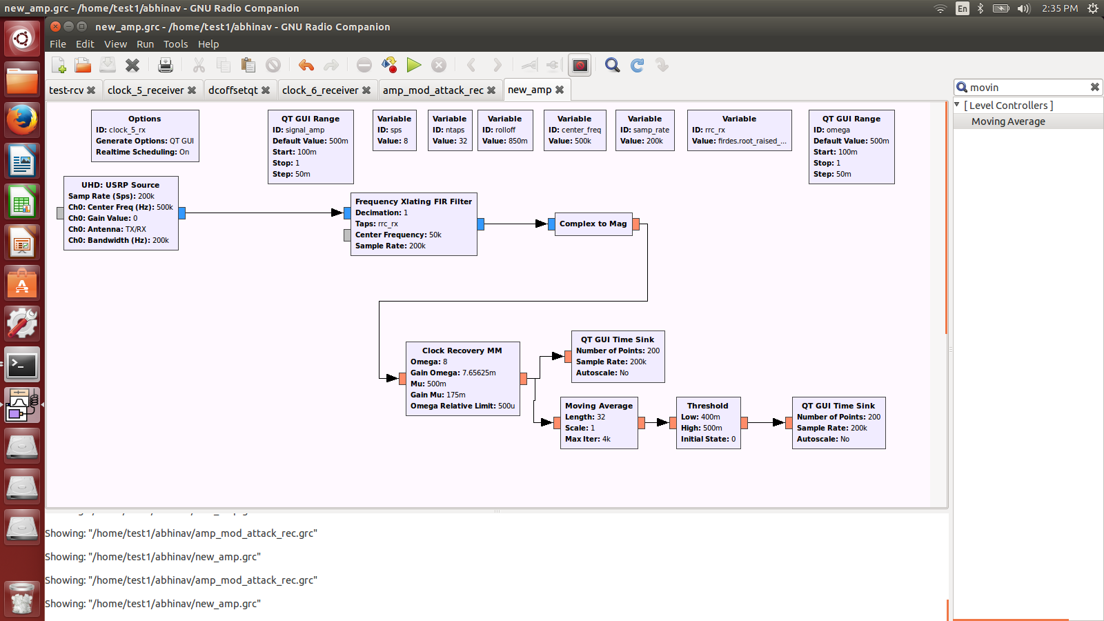
3) I tried AM_demod_freq_xlat.png which removes the FLL Bandedge, AGC2 so that there is more stability in terms of no noise amplication. I don't think this works at all as
a) I don't know the parameters to Xlat freq, I was bring my original signal at 500 KHz and 200 KHz BW(as in grc pic) to any lower frequency which I don't care as long as I get the demodulation.
b) I get DDDs undeflow for some reason.
c) I don't know what shall I put as the moving average filter length (must be pulse length, but I dont know if that is equal to the rrc_rx filter length or something else)
Please comment as currently I am out of ideas to try and make this work.
Thanks,
Abhinav