Dear Zhenghuai Guo,
I don't have experience in using high level assembly with transient problem, but it looks like your problem can be modelled as describedin http://getfem.org/userdoc/model_time_integration.html for Kelvin-Voigt linearized viscosity term. So, first you add classical linear elasticitybrick and then the second linear elastic brick on Dot_U for the viscosity term
Best regards,Andriy
On Sun, 24 Feb 2019 at 05:52, Zhenghuai Guo <address@hidden> wrote:
Hi Andriy,
In getfem, to model the Isotropic linearized elasticity described as below equation (1) and (2), we can use the “add_isotropic_linearized_elasticity_brick” or “add getfem::add_nonlinear_term” of the weak formulation.
(1)
(2)
Where
But what if we have a slightly modified question of (2) as below (3)
Where the
is the first order time derivative of strain.
Could you please advise how to model this? I try to add Grad_Dot_u in the weak formulation, but the getfem won’t allow me.
Thank you very much
Regards
Zhenghuai Guo
From: Andriy Andreykiv <address@hidden>
Sent: Friday, February 15, 2019 11:22 PM
To: Zhenghuai Guo <address@hidden>
Subject: Re: [Getfem-users] mesh_deformation
Dear Zhenghuai Guo,
First of all, please explain what exactly you are trying to do.
Do you want to prescribe a point force?
In Getfem you cannot add a point to a region, and you cannot define a source brick on a point.
Regions can contain only elements and element faces.
If you want to apply some pressure on top, then you apply a normal source term to a region with faces (but you already know that).
There is a way to prescribe a point force, but for that you need to add a so called explicit brick
where you specify a whole vector of forces for ALL degrees of freedom (DOF) of your model. So, to prescribe a point force you would set
all the DOF values to zero, but the one, corresponding to your point to the value you want.
But, this method is not very clean. May be, if you explain what exactly you are trying to model, I can suggest a better one.
Best regards,
Andriy
On Tue, 12 Feb 2019 at 02:46, Zhenghuai Guo <address@hidden> wrote:
Hi Andriy,
Thank you for the advice. My email before was not succinct enough I think for you to read. I found out what the problem was : the release distance was too small and after I increase it by enough amount, the program works.
Yes, the mass matrix is not necessary, since my problem does not have time gradient terms.
I now try to add a point source term to the problem. The mesh coordinates are a rectangular defined by two corner points (-0.5, 0) and (0.5,1).
I want to find the point closest to the point [0,1]. So I wrote the for loop to locate the target point on the mesh. The program did find out the target point [-1.37612e-12, 1] correctly (which is stored the p_find_out). Then I get its index by p_source_cv=mesh.search_point(p_find_out);
Then I added the point to the region (Point_source) by mesh.region(Point_source).add(p_source_cv);
Below is the part of codes to do the above operation.
size_type Point_source=960;
base_node p_target=base_node(0,1);
base_node p_find_out;
scalar_type p_distance=10 ;
scalar_type p_distance_temp;
size_type p_source_cv;
for (getfem::mr_visitor jj(border_faces); !jj.finished(); ++jj) {
assert(jj.is_face());
bgeot::pconvex_structure cvs = mesh.structure_of_convex(jj.cv());
cout << "Number of vertices: " << cvs->nb_points() << endl;
cout << "Number of faces: " << cvs->nb_faces() << endl;
for (bgeot::short_type f = 0; f < cvs->nb_faces(); ++f) {
cout << "face " << f << " has " << cvs->nb_points_of_face(f)<< " vertices " <<endl;
for (bgeot::size_type k = 0; k < cvs->nb_points_of_face(f); ++k){
base_node p =mesh.points_of_convex(jj.cv())[cvs->ind_points_of_face(f)[k]];
p_distance_temp=gmm::vect_dist2(p, p_target);
//////cout << p<<" " <<p_distance_temp<< endl;//////
if (p_distance> p_distance_temp){
p_distance=p_distance_temp;
p_find_out=p;
cout <<p_find_out<<" " << mesh.ind_points_of_convex(jj.cv())[cvs->ind_points_of_face(f)[k]] <<endl;
}
}
}
}
p_source_cv=mesh.search_point(p_find_out);
cout <<p_find_out<<" " << p_source_cv <<" " << mesh.points()[p_source_cv]<<endl;
mesh.region(Point_source).add(p_source_cv);
model.add_initialized_fixed_size_data("Dirichlet_value", base_small_vector(0,0.));
model.add_initialized_fixed_size_data("Fdata", base_small_vector(0.,-1000000));
getfem::add_Dirichlet_condition_with_multipliers(model, mim, "u", mf_u, Dirichlet_boundary_bot,"Dirichlet_value" );
cout << " add_Dirichlet_condition_with_multipliers" <<endl;
getfem::add_source_term_brick(model, mim, "u", "Fdata",Point_source);
cout << " add_source_term_brick" <<endl;
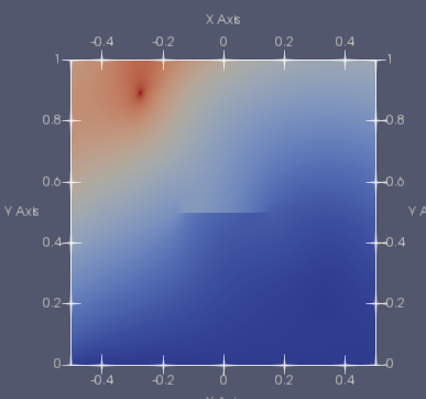
But after I ran the program, the point source seems be added in the wrong location as shown in the below picture. My desired point of source should be located in the top middle of the mesh.
Could you please advise? I can send you my full codes and the mesh if you think it is helpfull.
Thank you very much
Regards
Zhenghuai Guo
From: Andriy Andreykiv <address@hidden>
Sent: Monday, February 11, 2019 9:12 AM
To: Zhenghuai Guo <address@hidden>
Subject: Re: [Getfem-users] mesh_deformation
Dear Zhenghuai Guo,
Sorry I didn't reply earlier. Consider sending your email not only to me, but to all getfem-users, so that others can answer.
I would first try to run your problem without contact, just to see that you're applying the pressure correctly.
Double check what you're putting into your Fdata_top. Check if this value is not zero.
I also don't understand why you're adding mass brick. It's used in dynamics, to construct a mass matrix, but I don't think this is what you're looking for.
If you want to add weight, you'd need to add another source term on the volume region of your mesh.
That's how much I can tell without the code.
Best regards,
Andriy
On Mon, 4 Feb 2019 at 06:13, Zhenghuai Guo <address@hidden> wrote:
Hi Andriy,
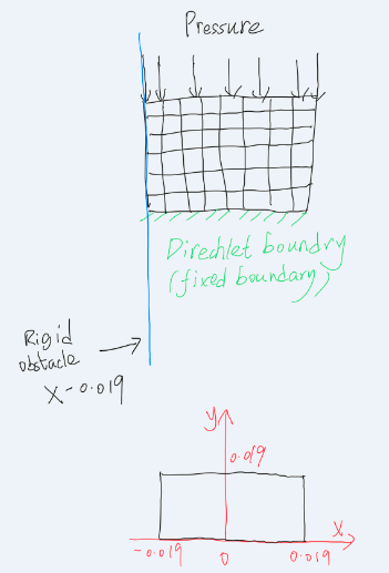
I try to use the technique of “add_integral_large_sliding_contact_brick_raytracing” in getfem, because I would like to eventually build two mesh and study their deformation with consideration of surface contact between them. I start by practicing with a simple test with only one mesh against a rigid obstacle, as the graph below. It is a 2D rectangular mesh, x_min = -0.019, x_max= 0.019, y_min =0, y_max = 0.019.
I applied elasticity by getfem::add_linear_term(model, mim,"(lambda*Trace(Grad_u)*Id(qdim(u)) + mu*(Grad_u+Grad_u')):Grad_Test_u" );
I also added a mass term by getfem::add_mass_brick(model, mim, "Dot_u");
For contact, I added ind = getfem::add_integral_large_sliding_contact_brick_raytracing(model, "1", release_dist, "f", "1", 0);
The bottom of mesh is set as Dirichlet_condition:
model.add_initialized_fixed_size_data("Dirichlet_value", base_small_vector(0,0.));
getfem::add_Dirichlet_condition_with_multipliers(model,mim, "u", mf_u,Dirichlet_boundary_bot,"Dirichlet_value");
And the rigid obstacle is set at “x+0.019” which is the vertical line x = -0.019. getfem::add_rigid_obstacle_to_large_sliding_contact_brick(model, ind, "x+0.019", N);
The mesh top is exerted by a pressure : getfem::add_source_term_brick(model, mim, "u", "Fdata_top",Neumann_boundary_top);
But, although the script seems running through ok (no error), the result appears like nothing happened. The stress and displacement is zero across the mesh.
Could you please advise about what could be the possible reasons? I have been trying to solve it for a while and I think my limited knowledge wouldn’t be able to help me anymore.
Thank you very much
Regards
Zhenghuai Guo
From: Andriy Andreykiv <address@hidden>
Sent: Monday, February 4, 2019 8:57 AM
To: Zhenghuai Guo <address@hidden>
Subject: Re: [Getfem-users] mesh_deformation
On Sun, 3 Feb 2019 at 13:06, Zhenghuai Guo <address@hidden> wrote:
Hi Andriy,
Thanks for you instruction. I now know how to select the faces and define the region I want depending on their coordinates.
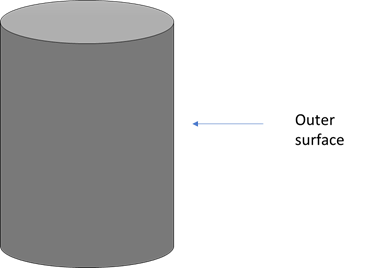
I guess my question is how to apply a pressure to the vertical external surface in the cylinder?
I used getfem::add_source_term_brick(model, mim, "u", "Pressure_value", Neumann_boundary_top); before for simple case where the pressure on each face are the same, as the normal vector of each face in the region are the same. For example, the horizontal external surface of the cylinder.
But now the face normal are not uniform within the region and the pressure on each face is dependent on the face normal. How can I apply the pressure/force on the this kind of region? Could you please advise?
Thank you very much
Regards
Zhenghuai Guo
From: Andriy Andreykiv <address@hidden>
Sent: Friday, February 1, 2019 10:50 PM
To: Zhenghuai Guo <address@hidden>
Subject: Re: [Getfem-users] mesh_deformation
Dear Zhenghuai Guo,
What you eventually want is to create a region inside the mesh with the faces that you selected and then apply boundary conditions to it.
If, for instance, you want to apply pressure to the vertical external surface of a cylinder I think the code could look like this
size_type OUTER_VERTICAL_SURFACE = 101; //unique region numbergetfem::mesh_region border_faces;getfem::outer_faces_of_mesh(mesh, border_faces);for (getfem::mr_visitor i(border_faces); !i.finished(); ++i) {base_node un = mesh.normal_of_face_of_convex(i.cv(), i.f());un /= gmm::vect_norm2(un);if (gmm::abs(un[2]) < 1.0E-7) { // Z component of the normal vector is smallmesh.region(OUTER_VERTICAL_SURFACE).add(i.cv(), i.f());}}//add_source_term_brick on OUTER_VERTICAL_SURFACE
On Thu, 31 Jan 2019 at 11:03, Zhenghuai Guo <address@hidden> wrote:
Hi Andriy,
I would like to apply a boundary condition to a cylinder outside surface. A boundary force P perpendicular to everywhere of the outside surface is applied.
I image the general steps may be as follows. But, I don’t know what to do after getting the norms of each faces of the region of interest. Could you please advise? Thank you very much.
getfem::mesh_region _border_faces;
getfem::outer_faces_of_mesh(mesh, _border_faces); //get outside boundary//
//then get norm of each faces in the _border_faces as a vector//
// ?? //
// add_source_term for the _border_faces //
Regards
Zhenghuai Guo
From: Andriy Andreykiv <address@hidden>
Sent: Wednesday, January 23, 2019 7:55 AM
To: Zhenghuai Guo <address@hidden>
Subject: Re: [Getfem-users] mesh_deformation
Please look at the very last code example at http://getfem.org/userdoc/bmesh.html
There you can see iteration over indices of a face. Having an index i you can get
node coordinates with mymesh.points()[i]
On Tue, 22 Jan 2019 at 13:41, Zhenghuai Guo <address@hidden> wrote:
Hi Andriy,
This is very helpful as I had been struggling about how to define region by node/points location.
I am trying to loop through a particular face to see the node/point coordinates. I can sort of get the first point in each face by doing the following.
for (getfem::mr_visitor i(_border_faces); !i.finished(); ++i) {
assert(i.is_face());
cout << mesh.points_of_convex(i.cv())[0] <<mesh.points_of_face_of_convex(jj.cv(),i.f())[0] << " " << i.cv() << " " << i.f() << endl;
}
But I can’t do the
for (getfem::mr_visitor j(mesh.points_of_face_of_convex(i.cv(),i.f())); !j.finished(); ++j) {}
Is that possible you can tell me how to get the total number of points in a particular face? So that I can loop through the object of ‘mesh.points_of_face_of_convex(jj.cv(),i.f())’.
Thank you very much
Regards
Zhenghuai Guo
From: Andriy Andreykiv <address@hidden>
Sent: Monday, January 21, 2019 10:57 PM
To: Zhenghuai Guo <address@hidden>
Subject: Re: [Getfem-users] mesh_deformation
Dear Zhenghuai Guo,
To created a region with the external faces of the mesh do:
mesh_region external_faces = outer_faces_of_mesh(my_mesh);
Sometimes you don't need the whole region, but only the top surface or something. Here is an example
code from laplacian_with_bricks.cc (in your tests directory) that goes through these faces and extracts
different ones depending on face orientation and location:
size_type N = 2; //problem dimension
getfem::mesh_region border_faces;
getfem::outer_faces_of_mesh(mesh, border_faces);
for (getfem::mr_visitor i(border_faces); !i.finished(); ++i) {
assert(i.is_face());
base_node un = mesh.normal_of_face_of_convex(i.cv(), i.f());
un /= gmm::vect_norm2(un); //normal to the face
if (gmm::abs(un[N-1] - 1.0) < 1.0E-7) { // second component of the normal is small, meaning the face is horizontal
mesh.region(NEUMANN_BOUNDARY_NUM).add(i.cv(), i.f());
} else {
mesh.region(DIRICHLET_BOUNDARY_NUM).add(i.cv(), i.f());
}
}
You can also iterate through the nodes of the particular face and see where it resides.
Best regards,
Andriy
On Mon, 21 Jan 2019 at 09:08, Zhenghuai Guo <address@hidden> wrote:
Hi Andriy,
Sorry but please neglect my previous email. What I would like to ask is as following.
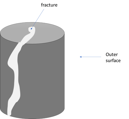
I have a cylinder like sample/mesh which is partially fractured and I would like to apply a traction on the outer surface by defining a Neumann boundary.
I find it hard to select the outer surface of the cylinder.
Could you please advise how to do it?
Thank you very much
Regards
Zhenghuai Guo
From: Zhenghuai Guo
Sent: Monday, January 21, 2019 6:51 PM
To: 'address@hidden' <address@hidden>
Cc: 'address@hidden' <address@hidden>
Subject: RE: [Getfem-users] mesh_deformation
Hi Andriy,
I have a cylinder like sample/mesh and I would like to apply a traction on the outer surface by defining a Neumann boundary.
I find it hard to select the outer surface of the cylinder.
Could you please advise how to do it?
Thank you very much
Regards
Zhenghuai Guo
From: Zhenghuai Guo
Sent: Tuesday, January 1, 2019 6:04 PM
To: 'address@hidden' <address@hidden>
Cc: address@hidden
Subject: RE: [Getfem-users] mesh_deformation
Hi Andriy ,
Thank you very much. I am using FEM_PK(2, 1) for now. I also use Salome for making meshes. Its output can be converted into .gmsh by GMSH then imported into getfem.
Happy new year
Regards
Zhenghuai Guo
From: Andriy Andreykiv <address@hidden>
Sent: Thursday, December 27, 2018 9:48 PM
To: Zhenghuai Guo <address@hidden>
Cc: address@hidden
Subject: Re: [Getfem-users] mesh_deformation
Dear Zhenghuai Guo,
Sorry for the late response. You're doing everything correct except your elements are not isoparametric, as temporary_mesh_deformator requires (this is it's current limitation, of course).
Geometric transformation of your elements is linear (you generated linear triangles with three vertices in GMSH), while the element type is FEM_PK(2, 2), meaning
that they have 6 degrees of freedom per element. You either need to create quadratic mesh in GMSH (it has a button "Order" or something), or, alternatively, you'd need to use FEM_PK(2, 1) linear interpolation
in your code.
Regarding the software I use for meshing. I used to use GMSH a lot as well. It does a good job once you learn it's ways. It's quite ok for reasonably small meshes. Now we use Getfem in our company and have our internal in-house mesher.
Best regards,
Andriy
On Mon, 17 Dec 2018 at 02:28, Zhenghuai Guo <address@hidden> wrote:
Hi Andriy,
Could you please again help me for the following?
- I generate an mesh from gmsh (‘Mesh_3.msh’ as attached). Then I run the code ‘myexperiment.cc’ as attached. It is basically for isotropic linear eleasticity.
Everything is fine if I delete the line 101 ‘auto deformator = getfem::temporary_mesh_deformator<getfem::model_real_plain_vector>(mf_u, U, true, false);’
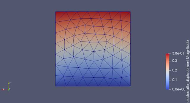
I can get a displacement field as in the figure below
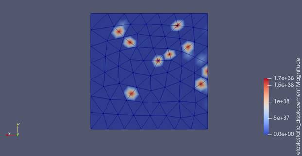
If I activate this line 101, then I get
Level 3 Warning in getfem_import.cc, line 233: All regions must have different number!
Mesh loaded
Mesh exported: 'mesh.vtk'
defined boundary: 'bound for whole boundary' 'Dirichlet_boundary for Dirichlet boundary' 'Neumann_boundary for Neumann boundary'
set fem mf_u: 'FEM_PK(2, 2)'
set mim mim: 'IM_TRIANGLE(2)'
model bullt: 'model'
add variable: 'u'
add scalar_data lambda, mu: 'lambda' 'mu'
add fixed_size_data Dirichlet_value, Fdata: 'Dirichlet_value' 'Fdata'
add_isotropic_linearized_elasticity_brick
add_Dirichlet_condition_with_multipliers
add_source_term_brick
Trace 2 in getfem_models.cc, line 4325: Mass term assembly for Dirichlet condition
Trace 2 in getfem_models.cc, line 4362: Source term assembly for Dirichlet condition
Trace 2 in getfem_models.cc, line 3446: Generic linear assembly brick: generic matrix assembly
Trace 2 in getfem_models.cc, line 4325: Mass term assembly for Dirichlet condition
Trace 2 in getfem_models.cc, line 4362: Source term assembly for Dirichlet condition
Trace 2 in getfem_models.cc, line 3293: Generic source term assembly
Trace 2 in getfem_models.cc, line 3300: Source term: generic source term assembly
Trace 2 in getfem_models.cc, line 3307: Source term: generic matrix assembly
condition number: 14972.4
model solved
terminate called after throwing an instance of 'gmm::gmm_error'
what(): Error in ../src/getfem/getfem_deformable_mesh.h, line 112 void getfem::temporary_mesh_deformator<VECTOR>::deforming_mesh_(VECTOR&) [with VECTOR = std::vector<double>]:
dimension of dof is greater than 3
and the displacement field is as in the below figure
I try to find out what the error means and solve, and I still can’t. The line 101 ‘auto deformator = getfem::temporary_mesh_deformator<getfem::model_real_plain_vector>(mf_u, U, true, false);’ is after line where I export the displacement field U, but the line 101 affect the export of U, which I don’t understand.
Could you please advise about this?
- Could you please let me know what software or approach you normally use for mesh generation for import to Getfem?
Thank you very much
Regards
Zhenghuai Guo
From: Zhenghuai Guo
Sent: Tuesday, December 11, 2018 12:15 AM
To: address@hidden
Cc: address@hidden
Subject: RE: [Getfem-users] mesh_deformation
Oh Thank you Andriy, I think I got confused by myself. The reason is that I already used getfem::vtk_export exp("mesh.vtk", false); above.
Then I do getfem::vtk_export exp("results/displacement_" + std::to_string(n) + ".vtk", false); It gave error of exp was previously declared.
Now it works. Thank you .
Regards
Zhenghuai Guo
From: Andriy Andreykiv <address@hidden>
Sent: Tuesday, December 11, 2018 12:02 AM
To: Zhenghuai Guo <address@hidden>
Subject: Re: [Getfem-users] mesh_deformation
" But in C++, I can’t repeatedly use getfem::vtk_export exp(filename, false) in each time step with a new filename value. "
Why? Yes you can. For instance, if you have a step number
int step;
and you increment it then you simply post-process inside the loop:
for (step = 0; step < NStep; ++step)
{
//calculation
getfem::vtk_export exp("result_" + std::to_string(step) + ".vtk", false);
}
Best regards,
Andriy
On Mon, 10 Dec 2018 at 13:57, Zhenghuai Guo <address@hidden> wrote:
Thank you Roman,
I will need to digest what you suggested and will let you know how it goes.
In the meantime, can you please advise: how to export a time series mf in .VTK format in C++.
In Python, it is quite easy using ‘model.export_to_vtk('results/displacement_%d.vtk' % n, U) ‘in each time step. The file names can be set to be displacement _1.vtk , displacement _2.vtk, displacement _3.vtk and so on.
But in C++, I can’t repeatedly use getfem::vtk_export exp(filename, false) in each time step with a new filename value.
Please advise.
Thank you very much
Regards
Zhenghuai Guo
From: Roman Putanowicz <address@hidden>
Sent: Sunday, December 9, 2018 8:17 PM
To: Zhenghuai Guo <address@hidden>
Cc: address@hidden
Subject: Re: [Getfem-users] mesh_deformation
Dear Zhenghuai Guo,
Probably this is not exactly what you requested, but I think can be helpful. Instead of dealing
with mesh connectivity you could use features of mesh_fem. To get the positions of points
on face you can do:
mesh_fem -> dofs_on_face -> poins related to dofs.
In mesh_fem there is a method:
ind_dof_face_ct getfem::mesh_fem::ind_basic_dof_of_face_of_elements(size_type_cv, short f);
It gives an array of dof numbers lying on a convex face.
Then you can use the method:
base_node::mesh_fem::point_of_basic_dof (size_type d);
The only thing to be careful is to properly select mesh_fem type, for instance Lagrangian one with
linear shape functions.
This way of getting points on face may seem strange but it is a direct use of GetFEM API
and you will not have do dig deeper into GetFEM internals.
Regards,
Roman
December 9, 2018 9:43 AM, "Zhenghuai Guo" <address@hidden> wrote:Hi Andriy,
Your advice help me a lot. I now try to make some simple c++ script in getfem. The compile and
build works fine.
I have one more question: how to get the points in a particular face, if we know the convex and
fact index?
I can see that we can do ‘mesh.convex(i).points()’ or ‘mesh.points()[i]’. But we can’t do
‘mesh.faces(i).points()’.
The reason I ask for this is that I would like to have the capacity to define region based spatial
coordinates.
Could you please advise?
Thank you very much
Zhenghuai Guo
From: Andriy Andreykiv <address@hidden>
Sent: Monday, December 3, 2018 5:12 AM
To: Zhenghuai Guo <address@hidden>
Cc: address@hidden
Subject: Re: [Getfem-users] mesh_deformation
Dear Zhenghuai Guo,
The installation and building of getfem and the tests are explained in the manual.
After getfem is installed, you can build all the examples with the command:
make tests
If you want to build a specific example, say laplacian_with_bricks, just type
make laplacian_with_bricks
The make script will call the compiler to build the object file and subsequently link it against
the library.
Your attempt to build elastostatic example is close, but not sufficient: you're compiling your
code, but not
linking against getfem. When you type "make laplacian_with_bricks", you will see the output of the
exact
commands necessary to compile and link against the library. You can use these exact commands to
build
your source file into an getfem based program.
Best regards,
Andriy
On Sat, 1 Dec 2018 at 21:16, Zhenghuai Guo <address@hidden> wrote:Dear Andriy,
I try your suggestions - using im_data for the coefficients - in python which are working fine.
Thank you very much.
But I still have problem in deforming the mesh in Python – simply don’t know how to call the
‘temporary_mesh_deformator’ in Python. I guess I should do it in C++.
I don’t really use C++ too much. Could you please let me know where the demos are for the C++?
I can see that in the folder ‘getfem-5.3/tests’, there are some ‘.cc’ test files – are they the
demos? I try to compile it : ‘g++ elastostatic.cc -o elastostatic’, but it did not go through (give
the message as attached). I am not sure if I did it right or simply because I did not install the
getfem right in the first place.
Could you please advise?
Thank you very much
Kind regards
Zhenghuai Guo
From: Andriy Andreykiv <address@hidden>
Sent: Wednesday, November 21, 2018 9:53 PM
To: Zhenghuai Guo <address@hidden>; address@hidden
Subject: Re: [Getfem-users] mesh_deformation
Dear Zhenghuai Guo,
For 1 you don't need to do anything. All the variables in the next step remain from the last step.
In some cases, if your variable has two versions (old and current, for instance) you need to call
model::next_iter() to copy all the old versions of variable to the current.
But if the variable doesn't have the two versions you don't need that. Normally we want to have two
versions of variables when our formulations use their increments.
For 2 you don't really need to add the linear elastic term with your own code, as the actual
function add_isotropic_linearized_elasticity_brick uses high-level assembly internally. Here is
it's source code
from getfem_models.cc
size_type add_isotropic_linearized_elasticity_brick(model &md, const mesh_im &mim, const
std::string &varname, const std::string &dataexpr1, const std::string &dataexpr2, size_type region,
const std::string &dataname3) { std::string test_varname = "Test_" +
sup_previous_and_dot_to_varname(varname); std::string expr1 =
"((("+dataexpr1+")*(Div_"+varname+"-Div_"+dataname3
+"))*Id(meshdim)+(2*("+dataexpr2+"))*(Sym(Grad_"+varname +")-Sym(Grad_"+dataname3+"))):Grad_"
+test_varname; std::string expr2 = "(Div_"+varname+"*(("+dataexpr1+")*Id(meshdim))"
+"+(2*("+dataexpr2+"))*Sym(Grad_"+varname+")):Grad_"+test_varname; ga_workspace workspace(md,
true); workspace.add_expression(expr2, mim, region); model::varnamelist vl, vl_test1, vl_test2, dl;
bool is_lin = workspace.used_variables(vl, vl_test1, vl_test2, dl, 2); if (is_lin) { pbrick pbr =
std::make_shared<iso_lin_elasticity_new_brick> (expr2, dataname3); model::termlist tl;
tl.push_back(model::term_description(varname, sup_previous_and_dot_to_varname(varname), true)); if
(dataname3.size()) dl.push_back(dataname3); return md.add_brick(pbr, vl, dl, tl, model::mimlist(1,
&mim), region); } else { return add_nonlinear_generic_assembly_brick (md, mim, dataname3.size() ?
expr1 : expr2, region, false, false, "Linearized isotropic elasticity (with nonlinear
dependance)"); }}
It's c++, but python logic would be similar.
Regarding the source code you've attached, I see that you still add the elastic constants as a
fixed size data. As I mentioned in the last email, you need to have different constants for every
integration point
of your model. Hence they have to be im_data.
Best regards,
Andriy
On Sun, 18 Nov 2018 at 20:47, Zhenghuai Guo <address@hidden> wrote:
Dear Andriy,
Thank you for the advice. You understand correctly about what I am trying to achieve. The problems
I am having now are to how to (1) use an updated deformed mesh and (2) consider the
displacement/stress value of previous timestep as the initial condition at each new time step.
Could you please advise about the following?
* If I use Isotropic_linearized_elastic_brick, how can I pass the displacement and stress values
from one time step to another? At each timestep, I would like the initial condition to take into
account the state (e.g. displacement and stress) of last timestep. I am not sure maybe it does it
automatically or not.
* I am trying to use high level assembly string language to carry out linear elasticity. I am
guessing, by doing this I can be more free. And maybe I can consider the displacement/stress value
of previous timestep as the initial condition at each new time step.
Could you please have a look at the attached small code? I try to add the assembly string of
isotropic linear elasticity by md.add_linear_term(mim,'(clambda*Trace(Grad_u)*Id(qdim(u)) +
cmu*(Grad_u+Grad_u’)):Grad_Test_u ')
but, when I run the code, it appear with some problem – although it does not give error, but it
does not proceed and the python shell is restarted. Could you please advise about this issue?
Thank you very much
Regards
Zhenghuai Guo
From: Andriy Andreykiv <address@hidden>
Sent: Friday, November 16, 2018 11:03 PM
To: Zhenghuai Guo <address@hidden>
Cc: address@hidden
Subject: Re: [Getfem-users] mesh_deformation
Dear Zhenghuai Guo,
If I understand correctly, you're trying to model creep with contact. If so, then you can probably
assume that your elastic properties are weakly coupled with stress. In that case you can probably
just update your elastic properties every time step.
So, you need to write a loop where you change the properties every step. Here are some ideas
1) Your elastic properties lambda and mu cannot be fixed sized constants, as they will depend on
stress values throughout the domain. The logical way to handle this is
by setting them as a so-called im_data, which is a field defined on Gauss points (on mesh_im
class). Please look up documentation or source how to add im_data.
2) Isotropic linearized elastic brick does not compute and store stress field. You will need to
define stress field as im_data too and compute it from your solution
using probably high-level assembly syntax
ga_interpolation_im_data(md, "lambda*Trace(Grad_u)*Id(qdim(u)) + mu*(Grad_u+Grad_u'))" , im_data
&imd_stress, base_vector &stress_result_vector);
3) The whole calculation should look like this:
initialize the elastic properties as im_data
create im_data for the stress
add contact bricks
while(t < T)
{
md.solve();
compute the stresses from the displacement field using high-level assembly syntax interpolations
compute the new values for the elastic properties with high-level assembly syntax interpolations
post-process;
t = t + delta T;
}
Best regards,
Andriy
On Fri, 16 Nov 2018 at 04:42, Zhenghuai Guo <address@hidden> wrote:
Dear Andriy,
I am planning to do a time dependent deformation with consideration of the contact and friction. I
would like to apply the elasticity theory with Young’s modulus being a function of time and local
stress value.
Could you please advise about the following?
* If I use add_isotropic_linearized_elasticity_brick (mim, varname, dataname_lambda, dataname_mu,
region=None), how can I make the Young’s modulus time and stress dependent? In the test examples
e.g. in demo_tripod.py, Young’s modulus is only added by the method add_initialized_data as a
constant scalar value.
* If I carry out elasticity formulation by a approach like the one in demo_tripod_alt.py using low
level approach to building the linear system by hand, can I in the meantime apply together the
bricks framework e.g. add_master_contact_boundary_to_large_sliding_contact_brick(indbrick, mim,
region, dispname, wname=None)?
Thank you very much
Best regards
Zhenghuai Guo
From: Andriy Andreykiv <address@hidden>
Sent: Thursday, November 8, 2018 8:56 PM
To: Zhenghuai Guo <address@hidden>
Cc: address@hidden
Subject: Re: [Getfem-users] mesh_deformation
Dear Zhenghuai Guo,
You can build getfem and getfem based programs using either GCC c++ compiler for Linux based
systems
(read Page 5 of the user doc:
http://download-mirror.savannah.gnu.org/releases/getfem/doc/gmm_userdoc.pdf)
or with Microsoft Visual Studio (you can use free Community edition). You can find MSVC solution in
msvc directory of the distribution.
Unfortunately, the solution for MSVC is not kept up-to-date and you would need to re-add all getfem
sources to it to make it work.
You can deform your mesh with a simple call:
auto deformator = temporary_mesh_deformator(mf, U, true, false);
//the first true means "deform on creation", the second false means "do not restore the mesh back
when temporary_mesh_deformator reaches the end of life"
mf - is the mesh_fem for your displacement field and U is the displacement vector with
gmm::vect_size(U) = mf.nb_dof();
Best regards,
Andriy
On Thu, 8 Nov 2018 at 01:15, Zhenghuai Guo <address@hidden> wrote:
Dear Andriy,
Thank you for your explanation.
Regarding creep, at the moment I only use liner_elasticity_brick with young’s modulus being changed
on each time-step. This is just to start with. I am new in Getfem in fact.
Could you please advise about the follows?
* Are you using c++ to run getfem? If so, can you give some hints how I can to it? I can’t see any
instruction about setting up for c++.
* If you don’t use c++, how do you normally use the getfem::temporary_mesh_deformator (from
getfem_deformable_mesh.h) or other C functions?
I was trying to see if it is possible to use this function in Python interface by using SWIG or
Python.Boost. But it is far beyond my knowledge.
Thank you very much
Regards
Zhenghuai Guo
From: Andriy Andreykiv <address@hidden>
Sent: Wednesday, November 7, 2018 8:32 PM
To: Zhenghuai Guo <address@hidden>
Cc: address@hidden
Subject: Re: [Getfem-users] mesh_deformation
Dear Zhenghuai Guo,
I don't use Python interface much, but your assumption is correct, using
getfem::temporary_mesh_deformator (from getfem_deformable_mesh.h) you can apply displacement field
to the mesh.
By default temporary_mesh_deformator will deform the mesh and un-deform it in the destructor,
unless you build it with the argument to_be_restored=false.
I only assume that you can do it with Python too.
I'm not really experienced with creep, but intuitively I would assume that you can also use large
deformation formulation to account for the change in geometry.
Or it's not how you intend it?
In your follow up email you are asking about the usage of mesh slices. From what I know it's used
primarily for post-processing, not calculation. If you intend to use it solely for
post-processing than you can easily achieve it nowadays with Paraview, were you import a vtk file,
warp the result with a displacement field and take a desired slice.
Best regards,
Andriy
On Sat, 3 Nov 2018 at 12:33, Zhenghuai Guo <address@hidden> wrote:
Dear Sir or Madam,
Could you please advise how I and deform a mesh according to a displacement field?
I am trying to simulate a time dependent deformation of a cylinder like object using
python-interface. After applying stress the object creeps with time.
I think I can just go with many small time steps. In each time step, I would like to update and
deform the mesh according to the displacement calculated as a function of time. And the deformed
mesh will be an input for next time step.
I can see there is some related information such as (1) ‘getfem_deformable_mesh.h’ in page 18 in
https://download-mirror.savannah.gnu.org/releases/getfem/doc/getfem_project.pdf (2)
‘getfem::slicer_apply_deformation’ in
http://getfem.org/userdoc/export.html#getfem::slicer_apply_deformation . But I can find details
examples.
Thank you very much
Zhenghuai Guo
Tyree Xray CT network facility, School of Minerals and Energy Engineering Resources, UNSW Sydney
- - - - - - - - - - - - - - - - - - - - - - - - - - - -
Roman Putanowicz, PhD <address@hidden>
Institute for Computational Civil Engng (L-5)
Dept. of Civil Engng, Cracow Univ. of Technology
www.l5.pk.edu.pl, tel. +48 12 628 2569, fax 2034
--

  Yves Renard (address@hidden)       tel : (33) 04.72.43.87.08
  INSA-Lyon
  20, rue Albert Einstein
  69621 Villeurbanne Cedex, FRANCE
  http://math.univ-lyon1.fr/~renard

---------