Description: JPEG image
|
| From: | Justyn Bell |
| Subject: | Re: [Discuss-gnuradio] USRP N210 Benchmarks. |
| Date: | Tue, 22 Nov 2011 15:54:49 -0800 |
Hey guys, sorry for the extremely late response. Although identifying and solving USRP problems is great, our focus lies in the project at hand.
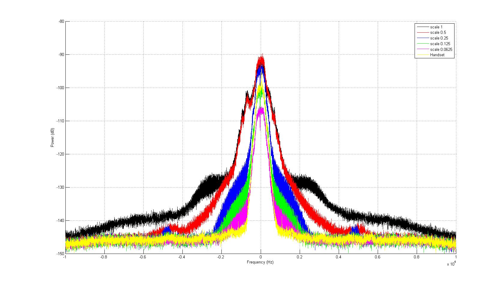
That being said, the responses on here were great. We tried scaling the input signal magnitude and it actually worked very well. The perplexing thing, however, is that the more we scale the magnitude, the better the observable spectrum got. There was no point in which scaling the magnitude didn't show at least a little improvement on the spectrum. I have attached the spectrum of our actual P25 waveform with scaling. Also included in that figure (yellow) is a signal captured by the USRP that was transmitted using an EF Johnson handset with a P25 waveform installed. Clearly the EF Johnson's spectrum looks the best, and although we didn't try scaling our data further than by .0625, the signal decreases in strength. At some point the signal must be too weak to transmit without both compromising the SNR and the "granularity" or resolution of the original signal (if that's the appropriate word to use).
The biggest thing I am considering is this: we are using a 12.5kHz channel on a daughterboard whose range is between 50MHz to 2.2GHz. Is such a narrowband signal on such a wide band board problematic?
Although the spectrum looks great when scaled, when we actually test our waveform from USRP to USRP we still get bit errors. Again, it's hard to say how many because we are utilizing a waveform that is equipped with a software vocoder, encryption (small bit errors mean huge losses in packets we receive) and forward error correction (should eliminate small bit errors). You can see how it is difficult to track down bit errors, but my personal opinion is that with forward error correction and the boxes sitting no more than 4 feet away from each other, there are enough errors to ruin our encrypted messages, and that's just too much.
We would very much like to use the very descriptive images you have provided in our work, if that's okay with you.
This is completely fine with all of us here, and thanks again for great responses. With the availability of so many USRPs (did I mention we have 2 USRP1s with the RFX daughterboards in them?) we can at least narrow things down a bit.
On Fri, Oct 28, 2011 at 5:08 AM, Marcus D. Leech <address@hidden> wrote:
Keep in mind also that spur and phase-noise performance of a PLL synthesizer will tend to
2011/10/27 Marcus D. Leech <address@hidden>
But what it points to is an *analog* issue, entirely independant of the CORDIC (which, as I observe, isn't likely involved in the test cases
Well, that sounds like the lazy solution, intermodulation products are bad, so just throwing the transmitter power away is not what I'd prefer.
at hand here).
Analog gain elements (including DACs) have operating regions over which they're linear, and operating regions over which they're not
linear. If you drive any amplifier near its maximum operating point, it will start to become non-linear to one degree or another. I'll
let Matt or one of the other engineering folks at Ettus comment further, but I personally am totally unsurprised when things start to
become non-linear near the nominal maximum operating point.Look at the tune_result_t from tuning:
Is there any way of finding out what the resolution is? We haven't been able to track it down for the RFX2400 board,but this sounds like a nice way to test if it _is_ the CORDIC.
http://files.ettus.com/uhd_docs/doxygen/html/structuhd_1_1tune__result__t.html
If the actual_dsp_freq is 0, then the CORDIC wasn't involved.
I tuned to an even number of MHz, which on all of the synthesizers *should* yield 0 CORDIC frequency.
But maybe Josh can add a feature to 'uhd_usrp_probe' to display the PLL resolution (although in some cases,
it may change with target frequency range, I think).
Thank yo very much for this, It is really usefull, and it furthermore confirms what we have observed.At 2.4GHz there is no problems, when we go 300 kHz up, we start seeing the problems. (see images attached)
This is further collaborated, with the fact that we can find "good" frequencies up through the entire band.
change with different tunings. Said performance on spot frequencies can be improved by
engaging in an optimization exercise involving not only PLL register settings, but changing
the analog loop filter on the PLL as well.
--
Principal Investigator
Shirleys Bay Radio Astronomy Consortium
http://www.sbrac.org
_______________________________________________
Discuss-gnuradio mailing list
address@hidden
https://lists.gnu.org/mailman/listinfo/discuss-gnuradio
--
Justyn Bell
![]() p25_spectrum.jpg
p25_spectrum.jpg
Description: JPEG image
| [Prev in Thread] | Current Thread | [Next in Thread] |